Quantcast
Channel: meter | Battery Guide
Viewing all 90 articles
Browse latest View live

Elektor 500ppm LCR meter case tips

$
0
0

I recently bought a 500ppm LCR meter from Elektor because I didn’t have anything for measuring inductors or the ESR (equivalent series resistance) of capacitors, both of which are important for modern electronics, particularly switch mode regulators that have become ubiquitous.
Elektor 500ppm LCR meter case tips
It is also more accurate than any of my multimeters and has wider measurement ranges. For example it can measure resistance from 0.1mΩ to 1GΩ and capacitance between 0.1pF and 0.1F. This means I can now measure parasitics like contact resistance, stray capacitance and lead inductance. The principal reasons it can do this while my multimeters can’t is because it uses a four wire Kelvin connection to the device under test, and as well as measuring voltage and current, it also measures the phase between them.

It took over a month to be delivered and the case arrived two weeks later. The meter’s arrival coincided with the arrival some ridiculously cheap switch mode buck and boost regulators from China. None of them worked properly (no surprise there) so it was pressed into service straight away, without its case. It worked well but when I got the case there were a few snags assembling it and then it then didn’t work properly.

The case comes pre-drilled and labelled from Elektor and is about three times the price of the generic version available from RS and Farnell. I expected it to include all the fasteners for that price but it only came with the screws that hold the case together.

To mount the LCD PCB I needed four M3 x 16mm countersink screws, nuts and washers and four 7mm M3 spacers.  Luckily I already had suitable screws and I used eight 6 BA x 1/8″ spacers as the LCD is actually 6.4mm only thick. If I hadn’t had those I would have printed some custom plastic ones.

I found the LED was too short to reach the hole for it in the front panel, so I re-soldered it as high as I could to improve its appearance. I also chamfered the back of the hole for it with a countersink to guide it in.

The next issue I had was the ribbon cable was way too long with nowhere to store the excess.

For more detail: Elektor 500ppm LCR meter case tips

The post Elektor 500ppm LCR meter case tips appeared first on PIC Microcontroller.


Electricity [Grid] Frequency Meter

$
0
0

An article by Dieter Laues in the February 2012 issue of Elektor inspired me to get my soldering iron out. The article described how by measuring the frequency of the mains electricity supply in any socket, the relative load across the entire electricity network could be determined. I ordered a pre-programmed processor (of the correct supply frequency) and built a meter for the electrical engineering department of the Further Education College I worked for at the time. When not being used in the classroom I would often switch it on in my workshop and stare at it,

Electricity Grid Frequency Meter

fascinated, as the LEDs travelled up and down as the load on the grid exceeded, and fell short of, the available supply. After leaving the College, I was sorry not to be able to monitor this and eventually became determined to build my own version. I decided to use a sixteen pixel by two line LCD display that would show the approximate supply voltage along with the frequency of the supply on the upper line of the LCD and the relative deviation of the frequency away from the nominal supply frequency as a bar graph on the lower line. The bar graph has a resolution of 0.025Hz (25mHz) per segment and indicates a lower than nominal frequency (and increased demand) by illuminating pixels to the left of the centre of the display and a higher than nominal frequency (increased supply) by illuminating pixels to the right of the centre of the display. When the grid is fully balanced and running at the nominal frequency, only the two centre elements of the LCD are lit. With sixteen pixels, each representing 0.025Hz the lowest frequency which can be displayed on the bar graph is the nominal frequency – (eight pixels x 25mHz) = nominal frequency – 200mHz, the highest displayable value being nominal frequency + 200mHz. The software within the program detects for nominal frequencies of

For more detail:  Electricity [Grid] Frequency Meter

The post Electricity [Grid] Frequency Meter appeared first on PIC Microcontroller.

Making a digital capacitance meter using microcontroller

$
0
0

Capacitors are one of the most common passive electrical components that are extensively used in all kinds of electronic circuits. In this project, we will discuss a technique of building a digital capacitance meter using a PIC microcontroller. This project can measure capacitance values from 1 nF to 99 ?F, with a resolution of 1 nF. The technique is based on measuring the time elapsed when a capacitor is charged to a known voltage through a series resistor. The microcontroller used in this project is PIC16F628A.

Making a digital capacitance meter using microcontroller

Capacitance meter

Theory

This capacitance meter is based on the principle of charging a capacitor through a series resistor. In a series RC circuit, as shown in the figure below, the voltage across the capacitor increases exponentially as it charges. Lets assume that initially the capacitor was fully discharged. When Vin is applied across the RC circuit, the capacitor starts charging and consequently, the voltage (Vc) across it increases from 0 towards Vin in an exponential way, as shown in the right side of the figure. The equation provided in the figure describes how the voltage across the capacitor changes with time. If we know the time that is required for the capacitor to charge up to a known voltage then we can solve this equation for C, knowing the value of R.

Schematic Making a digital capacitance meter using microcontroller

Capacitor voltage increases exponentially with time

The idea of measuring the time elapsed when the capacitor is charged from 0 to a known voltage can be implemented with any microcontroller. Here, we are using the PIC16F628A microcontroller, which has two built-in analog comparators. In this project, we are using the Analog Comparator 2 and TIMER2 modules to determine the time required by the capacitor to charge from 0V to 0.5Vin. The positive and negative inputs of the Analog Comparator 2 are externally accessible through RA2 and RA1 pins of PIC16F628A, respectively. In the figure shown below, two 2.2K resistors creates a voltage divider that sets the positive input (RA2) of the comparator to half of the voltage applied to RA0 pin. The negative input (RA1) of the comparator goes to the positive end of the capacitor through a 330? resistor. The resistor is used to discharge the capacitor prior to its measurement by setting RA1 low. When a voltage is applied to the RA0 pin, the capacitor (Cx), initially fully discharged, is charged through a 22K resistor. When the RA0 pin is just set high (say around 5V), the output of the comparator is high as the positive input of the comparator is at higher voltage (about 2.5V) than the negative input, which is close to 0V as the capacitor is fully discharged. Now the capacitor starts charging through the series resistor (22K) and when the voltage across it exceeds half of the voltage at RA0 pin, the comparator output is flipped to low. The comparator interrupt flag (CMIF) is set whenever there is a change in the output value of the comparator. The Timer2 module is used to compute the time elapsed between when RA0 is set high and the comparator output goes low. This is the time required by the capacitor to charge from 0V to half of the supply voltage.

For more detail: Making a digital capacitance meter using microcontroller

Current Project / Post can also be found using:

  • Digital capacitance metre theory

The post Making a digital capacitance meter using microcontroller appeared first on PIC Microcontroller.

TrH Meter: A DIY indoor thermometer plus hygrometer with adaptive brightness control implemented to 7-segment LED displays

$
0
0

This project is about building a microcontroller-based digital room thermometer plus hygrometer that displays temperature and relative humidity on 4 large (1 inch) seven segment LED displays which adjust their brightness level according to the surrounding illumination. It consists of a closed loop system that continuously assesses ambient light condition using an inexpensive light-dependent resistor (LDR) and uses that information to adjust the brightness of the display. An inexpensive DHT11 sensor is used to measure temperature and relative humidity. The microcontroller used in this project is PIC16F688, and it runs at 4 MHz clock generated from its internal source. A separate display driver chip (MAX7219) is used to control and refresh the display data on the seven segment LEDs.

TrH Meter A DIY indoor thermometer plus hygrometer with adaptive brightness control implemented to 7-segment LED displays

TrH Meter: A DIY indoor thermometer plus hygrometer

Why do we need adaptive brightness control?

Auto-adjusting the brightness of the seven segment LED displays not only saves power but also enhances the readability in all ambient lighting conditions. Many smartphones, HDTVs, PDAs, tablets, and computer screens now come with this feature. It basically dims the display in a dark environment and is still readable and eye-soothing. Similarly, when the ambient light level goes up, it brightens the display to enhance the readability. This project displays indoor temperature and relative humidity on large 1 inch seven segment LEDs that automatically adjust the brightness to be in balance with the light condition in the room. So, if you put this meter in your bedroom, you won’t have to worry about turning it off during nighttime. It will automatically dim low enough to not to disturb your sleep, while maintaining the readability.

Circuit diagram 

To make it easy to explain, I have divided the complete circuit diagram into 3 parts: Power supply unit, Microcontroller and sensor unit, and Display driver unit.

The power supply unit consists of a LM7805 regulator IC to derive regulated +5V power supply from a 9-15V DC wall adapter. The complete power supply unit circuit diagram is shown below. LED1 is a power-on indicator LED.

Schematic TrH Meter A DIY indoor thermometer plus hygrometer with adaptive brightness control implemented to 7-segment LED displays

Regulated +5V power supply unit

The following circuit diagram shows connections of the DHT11 sensor and the photoresistor (also called light dependent resistor or LDR) to the PIC16F688 microcontroller. DHT11 is a low cost digital sensor for measuring temperature from 0-50 °C with an accuracy of ±2°C and relative humidity ranging from 20-95% with an accuracy of  ±5%. The sensor provides fully calibrated digital outputs and has got its own proprietary 1-wire protocol for communication. I have described more about this sensor and its communication protocol in Measurement of temperature and relative humidity using DHT11 sensor and PIC microcontroller. The PIC16F688 uses the RC4 I/O pin to read the DHT11 output data. Note that R7 serves as the pull-up resistor required for the data pin of the DHT11 sensor. The S2 switch in the circuit diagram is to select between degree Fahrenheit (°F) and degree Celsius (°C) unit for temperature display. When the switch is open, the RC3 pin is pulled low by default, and the temperature is displayed in °F scale. In order to chose °C scale, the RC3 pin should be pulled high, which happens when S2 is closed.

For more detail: TrH Meter: A DIY indoor thermometer plus hygrometer with adaptive brightness control implemented to 7-segment LED displays

The post TrH Meter: A DIY indoor thermometer plus hygrometer with adaptive brightness control implemented to 7-segment LED displays appeared first on PIC Microcontroller.

Build a digital spirit level using a SCA610 accelerometer

$
0
0

A bubble or spirit level meter is a handy tool to find whether a surface is horizontal or vertical. It is often carried by civil engineers, mechanical engineers, surveyors, carpenters, and many other professionals whose work involve precise alignments of horizontal and vertical planes. Original spirit levels had two banana-shaped curved glass vials at each viewing point and were much more complicated to use. Mechanical spirit level meters are still available both in 1D and 2D formats. However at present time their electronic counterparts have also emerged and are even available in modern Android equipped cell phones. It’s from there I got my inspiration to make a very simple digital spirit level. Here’s a demo of such an electronic spirit level made by using a Microchip PIC16F684 micro, a SCA610 accelerometer and a handful of other discrete components.

Build a digital spirit level using a SCA610 accelerometer

Digital spirit level meter

Theory

The heart of this project is the SCA610 accelerometer IC that senses the inclination of a surface. Bases on VTI 3D MEMS technology, SCA610 is a very reliable, accurate and stable one-axis analog accelerometer. It requires a single power supply and provides an analog output voltage proportional to the inclination. According to its datasheet, if the device is powered with a precise +5.0V, the analog output voltages for +1g (vertical), 0g (horizontal), and -1g (vertical in opposite direction) inclinations would be 3.75V, 2.50V, and 1.25V, respectively. Voltages between 1.25V and 3.75V are linearly interpolated and mapped to the inclination angles varying from +90° to -90°. The analog signal can be processed by a microcontroller through an ADC channel to retrieve the inclination information.

Circuit diagram

The microcontroller used in this project is PIC16F684 which has just enough I/O pins and a built-in 10-bit A/D converter required for this project. The microcontroller runs at 8.0 MHz using the internal oscillator. The SCA610 sensor output goes to AN0 ADC channel of PIC16F684. The microcontroller takes quick multiple ADC samples which are averaged for a better estimation of inclination angle. There are five LEDs connected to RC0 through RC4 port pins and they are arranged in a row. Based on the direction of inclination the LEDs run in either forward or in reverse direction. There is a buzzer connected to RC5 pin which beeps continuously until the entire board settles at 0g or horizontal position. The buzzer used in the circuit is a ON/OFF type. What that means is it turns on when the RC5 pin goes high. If the device is aligned perfectly horizontal then only a central blue LED flashes and the buzzer mutes.

Schematic Build a digital spirit level using a SCA610 accelerometer

Circuit diagram of a simple LED spirit level meter (Click image to enlarge)

Software

The firmware for this project has been written in C using mikroElektronika’s mikroC Pro for PIC compiler. Note that the buzzer used in this project is a high impedance ON/OFF type and the software just turns the RC5 pin high in order to make the buzzer on. So this firmware won’t drive a buzzer that requires an ac signal. You can download the source code and compiled HEX output of the firmware from the following link.

For more detail: Build a digital spirit level using a SCA610 accelerometer

The post Build a digital spirit level using a SCA610 accelerometer appeared first on PIC Microcontroller.

Revised version of LM35 based digital temperature meter

$
0
0

This is a revised version of my LM35 based digital thermometer project that I posted last year. Although it is one of the simplest projects, it is very popular among newbies who are just starting to learn microcontrollers. There was a little flaw in the original project as pointed by some readers. I was using a 1.2 V reference for A/D conversion with PIC16F688 microcontroller. However, the PIC16F688 datasheet says Vref should be equal to or higher than 2.2 V to ensure 1 LSB accuracy of A/D conversion. Here, I am rewriting the same project but this time I am using a MCP1525 IC to generate a precise 2.5 V reference for A/D conversion. This will improve the accuracy of temperature measurements.

Revised version of LM35 based digital temperature meter

Interfacing LM35 temperature sensor with a PIC microcontroller

Theory

The LM35 series of analog temperature sensors are produced by National Semiconductor Corporation and are rated to operate over a -55 °C to 150 °C temperature range. These sensors do not require any external calibration. The output voltage is proportional to the temperature, and the temperature-to-voltage conversion factor is 10 mV per °C. The sensor does not have any DC offset output voltage (which means the output is 0V at 0 °C temperature) and therefore, a negative voltage source is required in order to measure temperatures below 0 °C. For simplicity, the setup shown here is made to measure temperatures above 0 °C only. The PIC16F688 microcontroller reads the analog output voltage from the sensor through one of its ADC channel and derives the temperature information out of it.

For the maximum temperature value of 150 °C, the output voltage of the sensor would be 150 x 10 mV = 1. 5 V. If we use Vref = 5.0 V (power supply voltage) for A/D conversion, the resolution would be poor as the input signal goes only up to 1.5 V. Besides, if the supply voltage is not stable, it won’t be a good idea to use it as  Vref for A/D conversion. Using a lower and more stable Vref voltage can improve both the resolution and the accuracy of A/D measurements. However, the datasheet of PIC16F688 microcontroller recommends to use reference voltage above 2.2 V to ensure 1 LSB accuracy of A/D conversion. The MCP1525 IC from Microchip provides a precise output voltage of 2.5 V, which could serve this purpose. This device is also available in TO-92 package, and therefore, it can be wired on a breadboard too.

Circuit diagram

The revised circuit diagram of the project is shown below. All the connections remain the same, except the two diodes and a resistor in the original circuit are replaced by a MCP1525 device.

Schematic Revised version of LM35 based digital temperature meter

Revised circuit diagram (click the image to enlarge)

The whole setup of this project is shown below. For illustrative purpose, I am using the LCD display from my I/O board project here. Don’t get confused with all the LEDs and tact switches on the board, they should be disregarded. I am only using the LCD part of it.

For more detail: Revised version of LM35 based digital temperature meter

Current Project / Post can also be found using:

  • rgb led binary clock using pic16f628a

The post Revised version of LM35 based digital temperature meter appeared first on PIC Microcontroller.

Weather meter using PIC 16F877 Microcontroller

$
0
0

Weather monitoring systems are available in plenty and these are pretty handy gadgets we use in our daily life for weather forecasting and other purposes. But these kinda gadgets might be expensive and may not be available for customization to our specified purpose. To overcome these advantages you can build this customized weather meter using PIC microcontroller which won’t cost much like those gadgets.

The system is built around PIC microcontroller where three parameters are measured in this system. Humidity,Temperature and ,Light intensity are the parameters this system takes as input to understand the weather condition. Then these parameters are displayed in the LCD screen for the user.

Weather meter using PIC 16F877 MicrocontrollerLM35 was used as a temperature sensor which is capable of sensing temperature ranging from -55 C to 150 C. The output voltage will be proportional to the temperature hence there is no need of trimmers. The output voltage of this sensor varies by 10mv per degree change in temperature.

Bought this Humidity sensor from a local store. The obtained output voltage is scaled to percentage and the reading in means of percentage is displayed in the LCD.

Simple LDR is used to measure the light intensity of the environment. Here LDR was used along with a resistor to form a voltage divider and the output is obtained from that divider. This output is also scaled to percentage and displayed in the LCD for the user.

Weather meter using PIC 16F877 Microcontroller Schematic

ALGORITHM:

  1. Initialize the LCD display.
  2. Display “H” , “L” and “T” which represents the parameters Humidity, Light intensity and Temperature.
  3. Define various weather conditions such as Sunny, rainy ,etc  for the expected sensor readings.
  4. Initialize the ADC Channels for the respective sensors.
  5. Read the sensor output one by one.
  6. Make appropriate conversion of the ADC value.
  7. Display the sensor values in the LCD display for the user.


For more detail: Weather meter using PIC 16F877 Microcontroller

Current Project / Post can also be found using:

  • weather meter using pic full components list

The post Weather meter using PIC 16F877 Microcontroller appeared first on PIC Microcontroller.

RAK8213 – The New Mini-PCIe Card For NB-IoT and LTE Cat M1

$
0
0

A China-based manufacturer called RAK Wireless has released the RAK833 LoRaWAN gateway module a couple months back. This has already been used hugely to create a gateway for ‘The Things Network’. Now they’re back with the new RAK8213, an NB-IoT and LTE Cat M1 module in the same mini-PCIe form factor as the RAK833. The RAK mini-PCIe card is constructed around the Quectel BG96 module, which provides both NB-IoT and LTE Cat M1 along with GNSS (GPS, GLONASS, Galileo, or BeiDou) support.

RAK8213 – The New Mini-PCIe Card For NB-IoT and LTE Cat M1

The mini-PCIe form factor is often associated with laptop computers, but recently we’ve started seeing that some single-board computers targeted at the maker market are also featuring this form. The Pine H64 single board computer is an example of it. Besides that, we’ve also noticed the rise of other mini-PCIe modules, such as the UP AI Core, or the PicoEVB, also aimed for makers.

This card can be added to netbooks/notebooks or routers in the mini-PCIe socket. It can be used for remote monitoringsmart meter reading, and so on. The user manual for this card basically explains how the user can send AT commands over USB or UART to the card in Windows, and how to set up the board with Hologram IoT SIM card.

RAK8213 is not the first NB-IoT/eMTC mPCIe card on the market. There are also some SIMCom SIM7000 based modules for about $30. However, it should be noted that the new RAK8213 works globally but SIM7000A / SIM7000C / SIM7000E work in specific regions, namely America, China and Europe.

Read more: RAK8213 – The New Mini-PCIe Card For NB-IoT and LTE Cat M1

The post RAK8213 – The New Mini-PCIe Card For NB-IoT and LTE Cat M1 appeared first on PIC Microcontroller.


Prepaid Energy Meter with GSM Modem using pic microcontroller

$
0
0

Prepaid Energy Meter with GSM Modem using pic microcontroller: The interfacing of prepaid energy meter with GSM (Global system for mobile) modem is very credible for both consumer and energy supply company. Basically, this is the concept of electronic energy meter for records the consumer billing, the minimization of energy theft and reducing the energy losses as compared to the conventional electromechanical energy meter.In this prepaid energy meter system, the consumer can pay the home billing through smart card or any other electronic resource such as mobile phone and save the time.Here we would be interface the energy meter with GSM module for prepaid energy meter billing, sending or receiving the massages or data to the supply company automatically. This interfacing system would be made with the help microcontroller 18 F452 belongs to pic family, energy meter, LCD display and GSM modem for sending or receiving the message or data automatically through mobile phone.

Page Contents

  • 1 Block Diagram of the interfacing of Prepaid Energy Meter with GSM Modem
  • 2 Components detail about the Interfacing of Prepaid Energy Meter with GSM Modem
  • 3  Working Principle Prepaid Energy Meter with GSM Modem
  • 4 Applications and Advantages of the Interfacing of Prepaid Energy Meter with GSM Mode

Block Diagram of the interfacing of Prepaid Energy Meter with GSM Modem

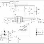
Figure 1 Block diagram of the interfacing of prepaid energy meter with GSM modem

Prepaid-energy-meter-using-gsm-and-pic-microcontroller

Components detail about the Interfacing of Prepaid Energy Meter with GSM Modem

The interfacing of prepaid energy meter with GSM modem system has following components list and working.

Transformer: For connecting, the interfacing of prepaid energy meter with GSM modem system to the wapda power supply a step-down transformer is required for step down the 220 V ac into 12 V ac. The transformer works on the principle of mutual induction and consists of two windings, primary and secondary.

Bridge Rectifier: The interfacing of prepaid energy meter with GSM modem system consists of electronics components, which are dc operated components therefore, a bridge rectifier is required which converts the ac voltages into dc voltages. This is connected at of transformer output.

Voltage Regulator:This interfacing of prepaid energy meter with GSM modem system consists of microcontroller LDC display, GSM modem and max 232, which are operated at 5 V dc. For supplying the 5 V dc a voltage regulator is used in this system at output of bridge rectifier. LM 7805 voltage regulator is used in this system.

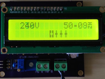
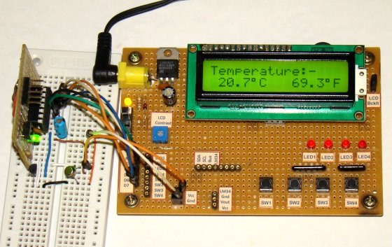
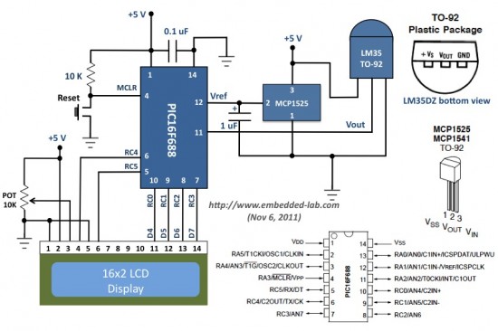
LCD Display: In this interfacing of prepaid energy meter with GSM modem system the LCD display is used for displaying the energy meter reading, consumer billing and the data which is sends by the consumer or supply company.

Microcontroller Pic 18F452:In this interfacing of prepaid energy meter with GSM modem system the Pic 18F452 microcontroller has been used here for the intelligent control of this system. The microcontroller consists of 40 pins and is interfaced with LCD display and GSM modem. This controller is programed in c language through the micko c software.  It collects the data or message, which is sends by the consumer mobile phone or supply company from GSM modem through the max232 and works accordingly to this data or message. It also collects the energy meter reading and display this on-LCD display.

Energy Meter:There are two types of energy meters are available in market one is the conventional energy meter, which works on the principle of mutual induction. This meter has rotating aluminum wheel that is called free wheel but this meter has so much energy losses. The second one is the electronics digital energy meter,which one is we are using here and is interfaced with the microcontroller. This meter has no moving parts and has low energy losses.

Max 232:This is 16-pins integrated circuit IC which is powered up by 5 V dc supply. In this interfacing of prepaid energy meter with GSM modem system, this IC is only used for communication purposes between the microcontroller and GSM modem. This is dual channel IC, means it can receive or send the data or message to microcontroller. This is basically the serial communication IC.

GSM Modem: The GSM modem is wireless base modem, which accepts the sim card and works on the principle of user mobile phone subscription. In the interfacing of prepaid energy meter with GSM modem system this is only used for communication purpose between the user mobile phone and this system.

 Working Principle Prepaid Energy Meter with GSM Modem

The working of this interfacing of prepaid energy meter with GSM modem system would be explain by connecting the lamp as a load at the output side of the energy meter. First, when we would be switch on this system then this would be asking for modem initialization. For modem initialization, we would dial the modem no. from any mobile phone and send the message to the system. By doing this the system has registered the mobile no. After this the system tells us kindly swipe the card. For card swiping we use the press button and set the cost. The cost setting is basically the pulses setting of the energy meter. Let’s suppose we set the cost 20 rupees and say the cost of 1 pulse is 2 rupees then actually we have settled 10 pulses. Now we switch on the output load that we have connected a lamp. When the lamp is on then the microcontroller, which is interfaced with the energy meter, counts the pulses of the energy meter and wait till for 10 pulses. When the 10 pulses have gone, then the microcontroller switch off the output load and sends the message to the user mobile phone through the GSM modem, that your balance has expired kindly recharge your card. This system also sends the reminder or warn message to the user mobile before the balance expired.

Read More Information….

Prepaid Energy Meter with GSM Modem using pic microcontroller

The post Prepaid Energy Meter with GSM Modem using pic microcontroller appeared first on PIC Microcontroller.

LCR PRO1 – LCR TWEEZER METER

$
0
0

LCR Pro1 from LCRresearch.com integrates a pair of tweezers like probes and a LCR meter into a single compact, lightweight, battery powered device. It is an all-in-one portable device that provides a simple and efficient solution for not only measuring SMD components but also making in-circuit debugging.

LCR PRO1 – LCR TWEEZER METER

LCR Pro1 delivers high accuracy once found only in high-end desktop LCR meters. It provides basic accuracy 0.1% for resistance and 0.2% for capacitance and inductance with 5-digit resolution. Each device is fully calibrated during production and shipped with NIST (National Institute of Standards and Technology) traceable calibration certificate.

The test frequencies can be selected from 100Hz to 100kHz. 100kHz is ideal for measuring small inductance under 1uH. The test voltage can be selected from 0.2Vrms to 1.0Vrms. 1.0Vrms allows precision measurements of ceramic capacitors with high dielectric constant (K), such as  X5R type. 0.2Vrms is specially designed for in-circuit debugging because it is low enough to prevent the silicon chips from being active during measurement.

Features

  • Easy operation – one hand use, full set of shortcuts
  • Fully auto/manual selection
  • High accuracy – R: 0.1%, L: 0.2%, C: 0.2%
  • 5 test frequencies – 100Hz, 120Hz, 1kHz, 10kHz, 100kHz
  • 3 test voltages – 0.2Vrms, 0.5Vrms, 1.0Vrms
  • Wide measurement range – R: 20mΩ to 10MΩ, C: 0.1pF to 10mF, L: 10nH to 1H
  • Small size – 151 x 19 x 15mm
  • Large OLED display – 0.96″, 128 x 64 resolution
  • Ultra precise gold plated tips
  • Rechargeable LiPO battery with USB charging
  • PC remote control for data logging and programming
  • Multiple functions – R, L, C, Z, ESR, DCR, D, Q, θ, diode, sorting, recording and continuity

LCR Pro1 comes with a 0.96″ OLED display, doubling the size of its predecessor’s 0.91″ display. The pixels are doubled as well from 12832 to 12864. Larger font and more information can be displayed for you to read the results and navigate the menu more conveniently.

Read more: LCR PRO1 – LCR TWEEZER METER

The post LCR PRO1 – LCR TWEEZER METER appeared first on PIC Microcontroller.

FAST AND COST-EFFECTIVE EVALUATION OF THE MASS FLOW METERS SFM3XXX-AW AND SFM3XXX-D

$
0
0

Sensirion, the worldwide leading manufacturer of high-quality flow and environmental sensors, is launching a new evaluation kit. With the EK-F3x-CAP, expiratory and proximal sensors of the SFM3xxx platform can be tested quickly and easily. The evaluation kit works with both the disposable and reusable variants of the flow sensors.

FAST AND COST-EFFECTIVE EVALUATION OF THE MASS FLOW METERS SFM3XXX-AW AND SFM3XXX-D

The EK-F3x-CAP evaluation kit offers a simple and cost-effective way to test sensors of the SFM3xxx platform. The set consists of a USB cable which connects to the corresponding flow meters. Using the software available online, the sensors can be quickly tested under real-life conditions. There is no need to program a microprocessor as the evaluation kit can be directly connected to a PC. The software shows the measurement data directly on the user’s computer screen. Furthermore, the data can be exported into an Excel spreadsheet which can then easily be saved and further processed.

The Sensirion SFM3xxx platform includes sensors for inspiratory, expiratory and proximal flow measurement, as well as gas mixing in ventilation and anesthesia applications. With the platform, the sensor manufacturer offers its customers the right sensor for all flow measurements and underscores its worldwide expertise in the field of medical ventilation. The reusable “AW” versions are autoclavable and washable, and therefore well-suited for expiratory flow measurement. The disposable “D” versions are a safe and cost-effective alternative to reprocessing.

Like all sensors from Sensirion, the outstanding performance of the SFM3xxx sensors is based on the patented CMOSens® Technology. This enables integration of the sensor and evaluation circuit on a single CMOS silicon chip. The result is an ultra-precision system that offers long-term stability for sophisticated and cost-sensitive applications. The technology is also highly resistant to environmental effects, which is why Sensirion’s flow sensors are perfect for use as sterilizable sensors.

Read more: FAST AND COST-EFFECTIVE EVALUATION OF THE MASS FLOW METERS SFM3XXX-AW AND SFM3XXX-D

The post FAST AND COST-EFFECTIVE EVALUATION OF THE MASS FLOW METERS SFM3XXX-AW AND SFM3XXX-D appeared first on PIC Microcontroller.

WITH THE NEW R&S NRX RF POWER METER, EVEN COMPLEX TEST SETUPS CAN BE CONFIGURED QUICKLY

$
0
0

Rohde & Schwarz has equipped the new RF power meter with a touchscreen based operating concept that guides the user through configuration. The R&S NRX has up to four measurement channels, for which Rohde & Schwarz offers a wide range of power sensors. For the first time, both terminating and directional power sensors are supported in a single instrument.

WITH THE NEW R&S NRX RF POWER METER, EVEN COMPLEX TEST SETUPS CAN BE CONFIGURED QUICKLY

High-precision RF power measurement for modern applications is a challenge. Rohde & Schwarz is launching the R&S NRX on the market so that users can transparently configure their measurements and perform them conveniently. The R&S NRX even makes it possible to perform triggered and synchronized multichannel measurements with different power sensors.

The user operates the instrument via the integrated high-resolution 5″ touchscreen. Measurements are configured using large buttons. The system supports the user with a logical calibration and draws attention to conflicts in case of doubt. If required, the instrument can also be operated using the buttons on its front panel.

The R&S NRX comes as standard with two robust sensor ports, which can be optionally upgraded to four. In addition, sensors can also be connected via USB or Ethernet.

Key Facts

  • Intuitive operation with touch screen based GUI
  • Supports up to four R&S®NRP and R&S®NRQ6 power sensors
  • Supports all sensor-dependent measurement functions
  • Optional high-precision CW and pulse mode reference source module
  • Optional power reflection measurements with NRT-Zxx sensors

Wide range of power sensors

The user can connect all terminating power sensors from the Rohde & Schwarz portfolio to the sensor connectors. The R&S NRX-B9 sensor interface module integrates the directional power sensors of the R&S NRT-Z family into the measurement to determine power in both transmission directions.

Reference generator integrated as a module

With the optional R&S NRX-B1 sensor check source module, users can test sensors for a pending measurement. The high-precision 50 MHz/1 GHz reference generator module generates continuous-wave signals as well as pulsed steep-slope signals.

Read more: WITH THE NEW R&S NRX RF POWER METER, EVEN COMPLEX TEST SETUPS CAN BE CONFIGURED QUICKLY

The post WITH THE NEW R&S NRX RF POWER METER, EVEN COMPLEX TEST SETUPS CAN BE CONFIGURED QUICKLY appeared first on PIC Microcontroller.

SPLIT HOME ENERGY METER FEATURES ESP32 WITH MICROCHIP ATM90E32

$
0
0

Split Single Phase Energy Meter. Affordable remote energy monitoring for your entire home

The Split Single Phase Energy Meter can monitor the energy usage in your entire home in real time. It can easily be hooked up to an ESP8266 or ESP32 to wirelessly transmit energy usage data into a program like EmonCMS. It can also be used to monitor solar power generation to keep track of how much power you are making.

SPLIT HOME ENERGY METER FEATURES ESP32 WITH MICROCHIP ATM90E32

With The Split Single Phase Energy Meter You Can:

  • Save Money!
    • See exactly how much money is being spent on energy in real time
    • Find appliances that are using too much electricity
  • View & Gather Energy Data
    • View the energy usage of your entire home
    • Or track solar power generation
    • Review and graph historical energy data
    • View usage data in the EmonCMS Android or iOS apps
  • Be Informed!
    • Independent of your power company’s meter
    • Set up alerts for over or under usage
  • Not spend a ton on energy monitoring!
    • Built to be inexpensive but very accurate
    • Costs hundreds less than some other solutions

Specifications

  • Samples two current channels & one voltage channel (expandable to two voltage)
  • Calculates:
    • Active Power
    • Reactive Power
    • Apparent Power
    • Power Factor
    • Frequency
    • Temperature
  • Uses standard current transformer clamps to sample current
  • Includes built-in buck converter to power ESP8266, or ESP32
  • Two IRQ interrupts, and 1 Warning output
  • Energy pulse output (pulses correspond to 4 LEDs)
  • Zero crossing output
  • SPI Interface
  • Measurement Error: 0.1%
  • Dynamic Range: 6000:1
  • Gain Selection: Up to 4x
  • Voltage Reference Drift Typical (ppm/°C): 6
  • ADC Resolution (bits): 16
  • Compact size at only 40 mm x 50 mm

The project is going to be launched soon on www.crowdsupply.com. For updates, you can subscribe to the form on landing page.

Read more: SPLIT HOME ENERGY METER FEATURES ESP32 WITH MICROCHIP ATM90E32

The post SPLIT HOME ENERGY METER FEATURES ESP32 WITH MICROCHIP ATM90E32 appeared first on PIC Microcontroller.

CAPACITY METER CIRCUIT PIC16F873A

$
0
0

Capacity meter circuit 5pF and 2600uf between the condenser capacity can gauge the pic16f873 microcontroller and a few passive element and the circuit formed values of 2 × 16 LCD screen is displayed on… Electronics Projects, Capacity meter circuit PIC16F873A “microchip projects, microcontroller projects, “

CAPACITY METER CIRCUIT

Capacity meter circuit 5pF and 2600uf between the condenser capacity can gauge the pic16f873 microcontroller and a few passive element and the circuit formed values of 2 × 16 LCD screen is displayed on the software assembly prepared by the source asm code description in the measurements performed on may be useful project ..

CAPACITY METER CIRCUIT(1)

CAPACITY METER CIRCUIT(2)

Source: CAPACITY METER CIRCUIT PIC16F873A alternative link: capacity-meter-circuit-pic16f873a.rar

The post CAPACITY METER CIRCUIT PIC16F873A appeared first on PIC Microcontroller.

LCD SWR METER CIRCUIT PIC16F877

$
0
0

SWR meter circuit pic16f877 microcontroller with lcd display displays the information on a printed circuit board with 2 × 16, schema diagrams in the C source code library files (adc. c, lcd8 c, swrm…. Electronics Projects, LCD SWR Meter Circuit PIC16F877 “microchip projects, microcontroller projects, pic16f877 projects, “

LCD SWR METER CIRCUIT

SWR meter circuit pic16f877 microcontroller with lcd display displays the information on a printed circuit board with 2 × 16, schema diagrams in the C source code library files (adc. c, lcd8 c, swrm. c, timers), and I have 2 different hex code for 16f877a 16f877

SWR METER CIRCUIT FEATURES

Power range 5-100W
Frequency range of 1-30 MHz
SSB operation for the Peak indicator
Forward, backward, power and SWR representation
Simple two-button interface
SWR warning and alarm LEDs

SWR METER CIRCUIT FEATURES (1)

SWR METER CIRCUIT FEATURES (2)

Source: LCD SWR METER CIRCUIT Alternatif link: lcd-swr-meter-circuit-pic16f877.rar

The post LCD SWR METER CIRCUIT PIC16F877 appeared first on PIC Microcontroller.


LOW COST HIGH ACCURACY STM32 FFT LCR METER

$
0
0

LOW COST HIGH ACCURACY STM32 FFT LCR METER

I have always wanted to build a fairly capable LCR meter that could cope with real world use in my own personal lab. This would mean reasonably good accuracy across a wide range of L, C and R. Fortunately, I got the time to do just that this year in the 3rd year Instrumentation module at my University. Although this justified spending time on such a project, I was motivated to do a good job so the end result would be usable as an actual piece of test equipment.

The approach I took was a mixed signal one where a capable analog front end would be paired up with a beefy DSP processor to compute the Impedance. Most importantly, in this scheme, the DSP is responsible for discriminating the phase between the sampled voltage and current waveforms; this approach is preferred because it leads to good accuracy and calibration stability.

The specifications and features were basically designed to mimic a commercial LCR meter. The test frequencies can be chosen from 1, 10 and 100 KHz and are all digitally synthesised. The software supports displaying L, C, R, Z and also an auto mode that classifies the DUT based on its impedance phase. The impedance measurement range with simple calibration has currently been tested from 0.1 Ohm to 10 MOhm with very good accuracy; this range is achieved by a highly reconfigurable analog signal path that allows about 100 voltage and current ranges, most of which are not used to allow easier calibration.

The LCD is a jelly bean 128×64 type and has been divided into a primary display consisting of the measured quantity and a secondary display showing the current measuring range and the impedance representation currently being displayed. The overall cost came to about £55.

Measurement Theory:

Passive Shunt:

The first method is the traditional and broadband technique commonly referred to as the “I-V method”. In this a resistive current shunt is placed in series with the DUT and the voltage across the shunt and the DUT are read off, allowing a calculation of Z.

However, this method has severe practical limitations described briefly below.

Limited I-V gain which is coupled to burden voltage: To keep the burden voltage of the shunt small, the shunt itself is typically, a few mOhms. As a result, I-V gain i.e. the differential voltage across the shunt is very small and on top of a much larger common mode signal. This places very strict performance requirements on the difference amplifier U1 and any subsequent gain stages. The only way to practically increase this signal is to increase the value of RSHUNT, which in turn increases the burden voltage. The source V1 then needs to be increased to keep VZDUT, often a strictly specified test parameter, constant

Read more: LOW COST HIGH ACCURACY STM32 FFT LCR METER

The post LOW COST HIGH ACCURACY STM32 FFT LCR METER appeared first on PIC Microcontroller.

SFM4300 – MASS FLOW METER FOR SENSITIVE GAS MIXTURE MEASUREMENT AT LOW FLOW RATES

$
0
0

The mass flow meter SFM4300 features improved sensitivity and precision, even for low flow rates.

SFM4300 – MASS FLOW METER FOR SENSITIVE GAS MIXTURE MEASUREMENT AT LOW FLOW RATES

The small, compact sensor is calibrated for air, O2 and N2O gases and – in contrast to its predecessor, the mass flow meter SFM4100 – it can also be used to monitor gas mixing. With a zero-point accuracy of 0.005 slm for a total range of up to 20 slm, the SFM4300 enables precise adjustment of the concentration in a wide selection of mixtures. The sensor unit has an I²C interface and produces a fully calibrated and temperature-compensated output signal. The mass flow sensor can be used for both medical and industrial gas mixing, fuel cells and for other OEM applications.

Features

  • Compact
  • High precision and sensitivity (esp. for low flow rates)
  • Flow range: 0 to 20 slm
  • Very pressure-resistant (up to 6 bar)
  • Multigas option: O2, air, NO2 (other calibrations on request)
  • Fully calibrated and temperature-compensated
  • Digital I²C interface
  • Mechanical connections: downmount, Legris, O-rings

Applications

  • Medical gas mixing: anesthesia, vaporizers
  • Industrial gas mixing: welding applications
  • Fuel cells
  • OEM applications

Flow Sensors for Gas Mixing in Respiratory Devices

In addition to inspiratory, expiratory and proximal flow measurement, Sensirion offers sensor solutions for gas mixing applications. These sensors are mainly used in anesthesia machines and are usually integrated into the overall machine. If we want to guarantee the patient’s safety while taking accurate, reproducible readings, we need the flow sensors in the machine to be stable and reliable – throughout the machine’s service life.  Therefore, the Sensirion SFM4000 series is the ideal solution. It is is devided in two sensors: SFM4300 and SFM4200. The SFM4300 sensor can operate at pressures of up to 6 bar, store multiple gas calibrations and even perform self-testing while in use. Where safety and reliability are concerned, the SFM4300 is the preferred choice. The SFM4200 sensor is highly resistant to pressure, it guarantees reliable measurements at surges of up to 8 bar. Its signal processing time is 0.5 ms, making it incredibly fast and accurate. Customers also benefit from an expanded measurement range of up to 160 liters per Minute.

Read more: SFM4300 – MASS FLOW METER FOR SENSITIVE GAS MIXTURE MEASUREMENT AT LOW FLOW RATES

The post SFM4300 – MASS FLOW METER FOR SENSITIVE GAS MIXTURE MEASUREMENT AT LOW FLOW RATES appeared first on PIC Microcontroller.

DSPIC30F4012 CONTROLS SPECTRO METER 10 BIT ADC IR FFT

$
0
0

Detailed Description – FFT Double Beam Infra-Red Spectrophotometer This original FFT double-beam IR spectrophotometer measures IR irradiation to identify varied chemical molecules. A dsPIC30F4012 controls the spectrometer with FFT algorithms. The 10-bit ADC on the DSPIC30F4012 has the cognition… Electronics Projects, dsPIC30F4012 controls spectro meter 10 bit adc ir fft “dspic projects, microchip projects, microcontroller projects,

DSPIC30F4012 CONTROLS SPECTRO METER 10 BIT ADC IR FFT

Detailed Description – FFT Double Beam Infra-Red Spectrophotometer This original FFT double-beam IR spectrophotometer measures IR irradiation to identify varied chemical molecules. A dsPIC30F4012 controls the spectrometer with FFT algorithms. The 10-bit ADC on the DSPIC30F4012 has the cognition to use VDD and VSS as references so you don’t requirement a secernate voltage write.

This program is designed to control a dual beam IR spectrometer

This program is designed to control a dual beam IR spectrometer. Inputs IR Signal (+-0.50 on 2.5VDC level) to 10 bit A/D Converter Quad Encoder (5VDC phase A and phase B) to QEA and QEB Temperature from MCP9700 (100mV to 1.75VDC ** -40C to 125C) Outputs Serial USB to PC (scan position, transmittance, temperature) PWM output filtered to 0 to 5VDC which is used to represent transmittance value LED 1 flashes at constant rate to verify process is running at correct speed (helps troubleshoot serial connection)

FILE DOWNLOAD LINK LIST (in TXT format): LINKS-10466.zip

Source: DSPIC30F4012 CONTROLS SPECTRO METER 10 BIT ADC IR FFT

The post DSPIC30F4012 CONTROLS SPECTRO METER 10 BIT ADC IR FFT appeared first on PIC Microcontroller.

ST-5S SMART TWEEZERS™ FOR ON-BOARD L/C/R MEASUREMENTS AND PCB TESTING

$
0
0

This intelligent measurement tool is a new type of handheld LCR meter that can quickly test, identify, and measure board-mounted surface-mount and leaded devices without the need to remove them from a circuit board.

ST-5S SMART TWEEZERS™ FOR ON-BOARD L C R MEASUREMENTS AND PCB TESTING

Saelig Company, Inc. has introduced the ST-5S Smart Tweezers™ for on-board inductance, capacitance, and resistance measurements and PCB testing.  The ST-5S tweezers are a valuable solution for quickly testing and identifying surface mount devices, as well as for troubleshooting complex electronic PCBs. Its unique mechanical and electronic design combines a pair of precise gold-plated tweezers and a digital LCR meter in compact, lightweight, battery-powered instrument.  Smart Tweezers™ automatically detects L, C, or R measurements and selects the correct measurement range and test frequency for high accuracy readings. Component type, value, and more detailed component analysis, such as Z and ESR, are all displayed on the instrument’s OLED display.

Surface mount devices are very small and have no wire leads, making it more difficult to test and identify SMDs than conventional leaded components. Smart Tweezers™ also gives users an easy way to sort tiny, loose components. Precise tips reliably contact even the smallest SMD components and take measurements from board-mounted devices. Smart Tweezers™ can also be used to test conventional components with wire leads that may not be long enough to insert into conventional test terminals. The integrated, insulated measurement head allows the operator to use one hand (left or right) for measurements to simplify probe placement tasks.

The ST-5S is for built for professional engineers since it comes with a NIST-traceable calibration certificate. The ST-5S allows users to change the test signal (with 0.5 and 1.0 Vrms), as well as variable tolerances of 1%, 5%, 10%, and 20%. This device also performs continuity and diode testing and shows active and reactive impedance component readings on the display.   A feature that saves time for users is that a semi-automatic offset subtraction feature automatically removes parasitic readings after set-up. The ST-5S is controlled by joystick-like navigation; pushing the button directionally will change the test mode, test signal, etc., and pressing the joystick directly opens a menu to allow more customized measurements and features such as changing the screen orientation.

Read more: ST-5S SMART TWEEZERS™ FOR ON-BOARD L/C/R MEASUREMENTS AND PCB TESTING

The post ST-5S SMART TWEEZERS™ FOR ON-BOARD L/C/R MEASUREMENTS AND PCB TESTING appeared first on PIC Microcontroller.

PIC16C622 MICROCONTROLLER MEASURING THE RESISTANCE CAPACITOR RC METER CIRCUIT

$
0
0

Based on PIC16C622 microcontroller circuit between 1Ω 999Ω resistance measurement between 1nF to 999 nF capacitor measurement yapılabiliry computer’s connection to the controller software pc software with assembly prepared with Visual Basic. PIC16C622 and application circuit microchip application notes… Electronics Projects, PIC16C622 Microcontroller Measuring the Resistance Capacitor RC Meter Circuit “microchip projects, microcontroller projects,

PIC16C622 MICROCONTROLLER MEASURING THE RESISTANCE CAPACITOR RC METER CIRCUIT

Based on PIC16C622 microcontroller circuit between 1Ω 999Ω resistance measurement between 1nF to 999 nF capacitor measurement yapılabiliry computer’s connection to the controller software pc software with assembly prepared with Visual Basic. PIC16C622 and application circuit microchip application notes all the details about the original formula is given.

RESISTANCE, CAPACITOR METER CIRCUIT SCHEMATIC

RESISTANCE, CAPACITOR METER CIRCUIT SCHEMATIC

The application circuit, called PICMETER, uses a PIC16C622 as a resistance and capacitance meter. The PICMETER uses a variation of the single-slope integrating converter. The linear slope and integrator of Figure 13 are replaced with the exponential charge waveform of an RC. The charge time of a known component is compared against the charge time of an unknown component to determine the value of the unknown component.

A schematic of the PICMETER is shown in Figure 16. All reference designators cited in this section refer to this schematic. Results are transmitted to a PC which displays the value measured.

PIC RC meter Circuit files:

FILE DOWNLOAD LINK LIST (in TXT format): LINKS-9194.zip

Source: PIC16C622 MICROCONTROLLER MEASURING THE RESISTANCE CAPACITOR RC METER CIRCUIT


The post PIC16C622 MICROCONTROLLER MEASURING THE RESISTANCE CAPACITOR RC METER CIRCUIT appeared first on PIC Microcontroller.

Viewing all 90 articles
Browse latest View live


<script src="https://jsc.adskeeper.com/r/s/rssing.com.1596347.js" async> </script>